
I’ve been looking at the best way to control relays using Home Assistant. My husband wanted an automated garage door opener, but something harder to hack than the average remote control and that we could remove in the summer when we’re not using it.
It could be done with a few smart plugs, but it would have been a mess of wires. Also, like in our case, if you already have bare wires or are handling DC power it’s more convenient to just plug your wires in a terminal and put everything in a box.
I’m also looking to reuse this for a few outdoor projects, and our WiFi network with an outdoor antenna has a lot more range than our ZigBee network.
The ESPHome platform already has all the necessary software elements to drive a board with a few relay, but no complete board with both an ESP8266 chip and the relay were available. I wanted something cleaner than that, so I set out to build my own PCB.
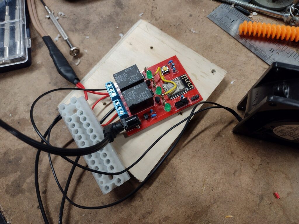
The hardware for the ESPHome relay board
The circuit itself has 3 main blocks:
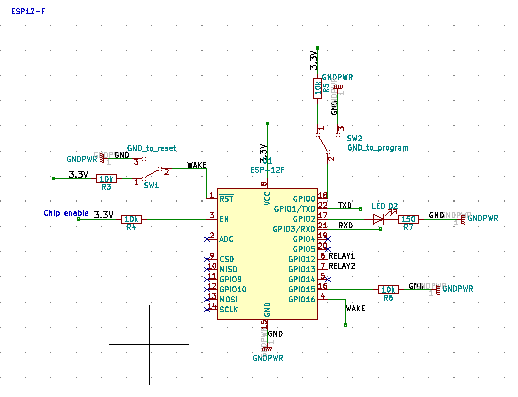
- The ESP8266 with its basic programming setup and reset switches, same as I had on my temperature/humidity sensor boards. I like to use the ESP-12F for this since they’re relatively easy to solder to a PCB with a hot air rework station. The ESP-12F boards are not always totally flat, but it’s nothing an extra bit of solder can’t solve.
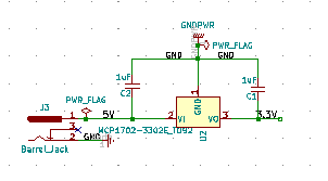
- I used the same MCP1702 voltage regular as my other project. It takes anything from 2.7V to 13.2V and outputs 3.3V, so most power supplies from my junk pile will work. I have the same barrel jack size as Arduino boards so I only need to keep one size around.
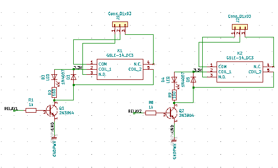
- The main part is the relay setup, with a transistor to help trigger it since the current from the ESP-12F is really low. The relay I choose can switch a max of 250 VAC or 125 VDC, so it can work for a wide range of projects. The circuit includes a LED that lights up when the relay is triggered, and a diode on the coil to protect the rest of the circuit from noise when the relay is cut off.
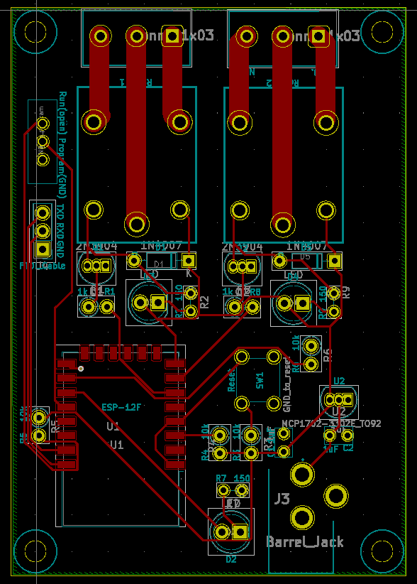
Finally, here is the finished PCB layout. I have large traces between the relay and the terminal block that can take up to 5A at the maximum voltage for the circuit (so less than the rating for the relay at 10A). More than this would require wires under the board; the required traces would be too wide to fit.
I also changed the location of a few part in that version version since I had to rewire the relay pins anyway: I moved the barrel jack at the bottom and added mounting holes.
Setting up ESPHome with the relay board
I’m not going to go through the whole ESPHome setup and programming flow here, you can refer to the excellent documentation ESPHome site for this.
I usually program by plugging the board to my laptop: the PCB has a FTDI header to connect via USB. The board must boot with the switch in the “program” position.
When your ESP8266 board is setup in ESPHome, you’ll need to add some extra info to set the relays before programming it. You’ll tell ESPHome that the device on the pin we use behaves like a switch, and give it a name for the Home Assistant entity. The inverted configuration allows you to set the relay to be on or off by default.
switch:
  - platform: gpio
    name: "Board 1 relay 1"
    pin:
      number: 12
      inverted: false
  - platform: gpio
    name: "Board 1 relay 2"
    pin:
      number: 13
      inverted: false
Once you’re done programming in ESPHome, you must switch the board back in “run” mode and reset it so it will execute the ESPHome code. It will then show up in Home Assistant as an entity under the “ESPHome” device and you can add it and use it like any other switch device.
For the full schematic, PCB layout and parts list, you can check out the KiCad Project here: https://github.com/CindyPotvin/WifiRelayESPHome