I’ve purchased an Ender 3 Pro 3D printer some time ago, but I only did a few demos prints at the time. I didn’t know where to start designing my own models, so the printer sat there collecting dust. The whole process of learning to model just to create a custom print sounded like a pretty big project.
I came back to it when I learned about some cool rooting balls for my gardening projects that were not available locally. Instead of buying them online, I started browsing Thingiverse a bit, but they were not the right size for what I wanted to do.
Since the shape was pretty easy, an empty sphere with an opening, I decided to bite the bullet and get around to it. I tried a few traditional drawing tools and it wouldn’t stick, but then I came across OpenSCAD. It’s a modeling tool that uses code to describe the object instead of drawing around with the mouse, which sounded perfect for a developer. I was a bit doubtful at first with the simple interface; it sounded too good to be true but I’m now hooked and keep drawing new projects!
This introduction will show you how to get started drawing your own 3D models with OpenSCAD. I will only show you the parts of the language that I believe are essential to get started quickly so you can print your own custom project in a few hours. The complete documentation at https://en.wikibooks.org/wiki/OpenSCAD_User_Manual/The_OpenSCAD_Language is also very good once you have played around with the software a bit.
Keep it mind that this tool is only to draw the 3D shape you want to print. To prepare the shape so it can be sent to a 3D printer, you need to import it in a slicer afterwards. I use the excellent slicer Cura for this, which has more options than the one that came with the printer.
Drawing 3D Shapes – Cube
OpenSCAD doesn’t require a lot of boilerplate. The minimal project is:
cube();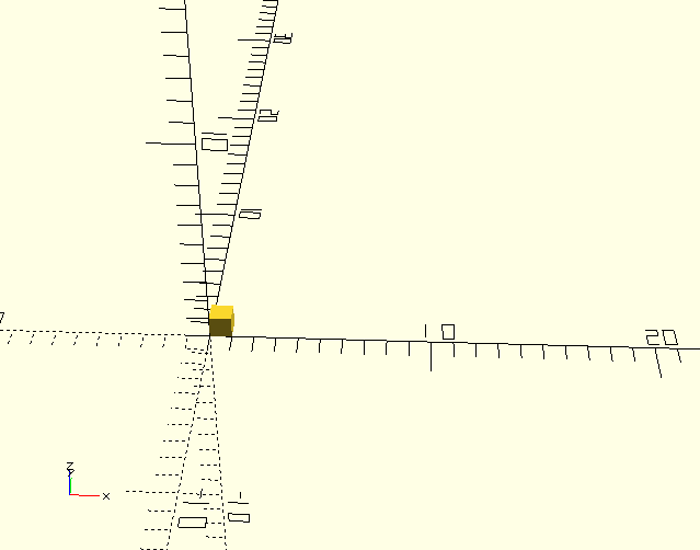
This draws a cube with a dimension of 1 on each side using the default values. Units are usually converted to millimeters when imported in a slicer to print the model, but they could be scaled to any size. OpenSCAD itself does not manage specific units.
You can render a preview of that cube using the Preview button, which is the first button under the preview area. Since it’s a preview and not a full render, it’s sometimes a bit imperfect, especially when you start subtracting shapes.
To make an interesting design, you’ll need to specify sizes. A more complete way to draw a cube would be:
cube(size = [5, 10, 10], center = false);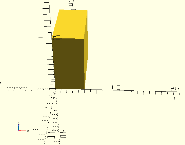
This draws a shape [x,y, z] with one corner on the origin (0, 0, 0). The parameters names, size and center in that case, can be included for clarity, but they are optional. Most shapes can take a variety of parameters, so you’ll often find yourself naming them.
If the center parameter was true, it would center the whole shape on the origin, instead of just a corner. Most shapes have a center parameter to control this, except the sphere (makes sense since a sphere doesn’t have a corner), so it depends on the model you’re drawing and your personal taste. This doesn’t change where the model will print since you can position it with the slicer later on.
Drawing 3D Shapes – Sphere and Cylinder
The other primitive shapes you’ll use a lot are the sphere and the cylinder. Here is a simple cylinder with a sphere.
$fn = 70;
diameter = 5;
cylinder(h = 10, d = diameter);
sphere(d = diameter);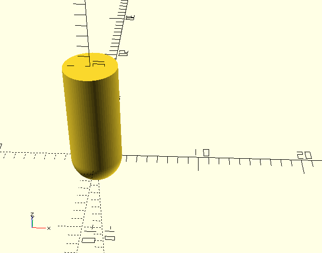
Where h is the height of the cylinder and d is the diameter. You can also use, among others, d1 and d2 if you need a different top and bottom diameter.
Here are also our first variables. The diameter variable could be named anything, but the $fn variable is a special variable that controls the number of fragments used to generate a circle. If it’s too low the sphere and cylinder will be blocky (and will print as such) but if it’s too high it’ll take a lot of time to render, so you may need to tune it depending on the precision needed your project. It can also be passed to each sphere and cylinder if you need a different precision.
That example is not very interesting yet since the cylinder and the sphere are on top of each other. We’ll usually need to move those shapes around a bit to draw something more interesting.
Transforming Shapes
To add a transformation to a shape, you need to add them in front of the shape and the instructions will then end with the function to draw the shape. For example, with our cube from earlier, we can translate it and flip it around, which makes for a decent example but a shape that would be very hard to print.
translate([0, 1, 1]) rotate([0, 45, 0]) cube();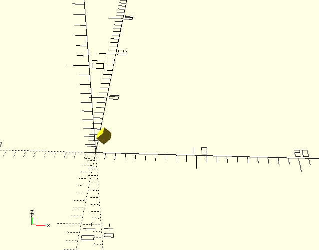
This style is a bit painful if we wanted to apply transformations to many shapes at once. Fortunately, you can also enclose a set of shape to which you want to apply an operation inside curly brackets ({}).
$fn = 70;
diameter = 5;
height = 10;
rotate([0, 90, 0]) {
   cylinder(h = height, d = diameter);
   translate([0, 0, height]) sphere(d=diameter);
}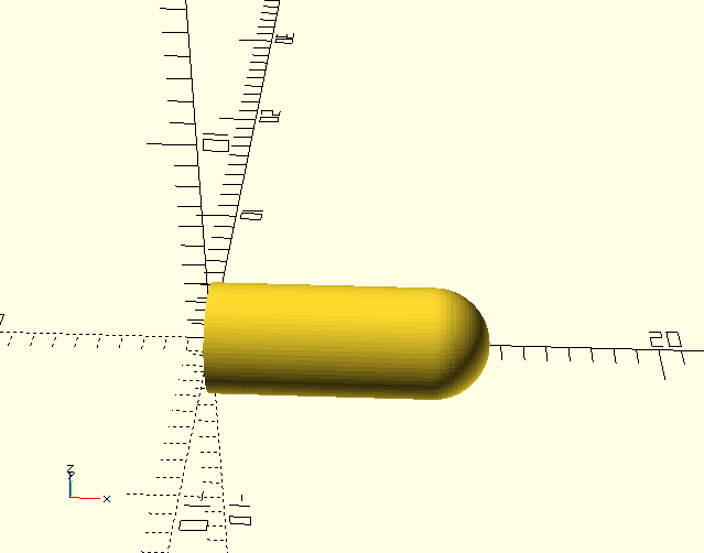
With this example, we now have a cylinder with a rounded top, and then we rotate the whole thing so it’s lying down.
Holes in Shapes
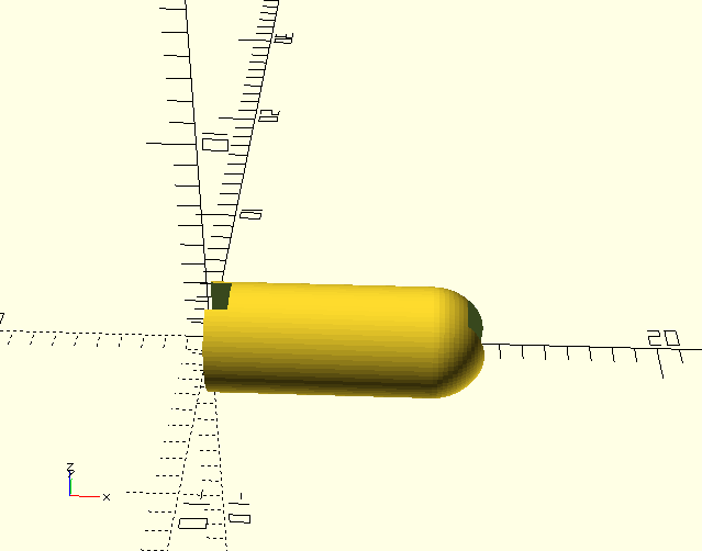
To create a hole in a shape, the easiest way is to subtract another shape from it. The difference function will take the result of the first instructions and remove all the following shapes in the curly brackets from it.
A quick tip: you can use # in front of any instruction so it’s highlighted in the preview. Handy if you don’t know where a shape ended up, or to see subtracted shapes!
$fn = 70;
diameter = 5;
height = 10;
holes = 2;
difference() {
  rotate([0, 90, 0]) {
     cylinder(h = height, d = diameter);
     translate([0, 0, height]) sphere(d=diameter);
  }
  translate([0, 0, 0]) cube([holes, holes, diameter], center=true);
  translate([height + diameter / 2, 0, 0]) cube([holes, holes, diameter], center=true);
}
Modules and Includes
Since big shapes can get a bit unwieldy, you can put that shape info a module so it can be reused as part of a bigger project. It will behave in the same was as the built-in shapes: you can specify default values to use, and also override those values as needed.
This will behave the same way as the previous example:
$fn= 70;
thing();

module thing(diameter = 5, height = 10, holes = 2) {
    difference() {
      rotate([0, 90, 0]) {
         cylinder(h = height, d = diameter);
         translate([0, 0, height]) sphere(d=diameter);
      }
      translate([0, 0, 0]) cube([holes, holes, diameter], center=true);
      translate([height + diameter / 2, 0, 0]) cube([holes, holes, diameter], center=true);
    }
}
Also, the include instruction allows you to import this module from another file, or to import other open source shapes you find!
include <thing.scad>

$fn= 70;

thing();
Conclusion
You can go a lot farther than this with OpenSCAD: all the common constructs you’re used to in a programming language such as loops and conditionals are also available. Surprisingly to a programmer you won’t find yourself using them a lot for most projects, using instead transformations and mathematical operations. The mathematical functions are also a lot richer than the small subset I presented to get you started. Still, this is enough to build many useful projects.