I’m building an Arduino project to automate growing oyster mushroom in a box. I can’t vouch for the results of growing the mushrooms yet, but the electronics are now complete, so I wanted to do a little writeup on it while it was fresh into my mind.
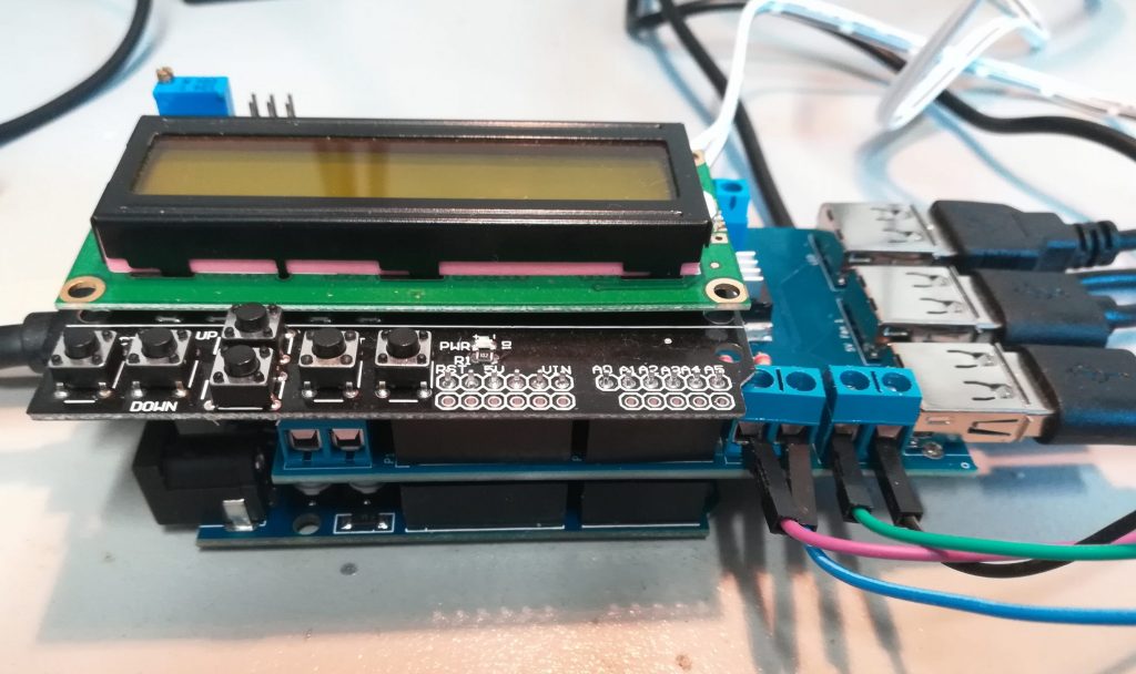
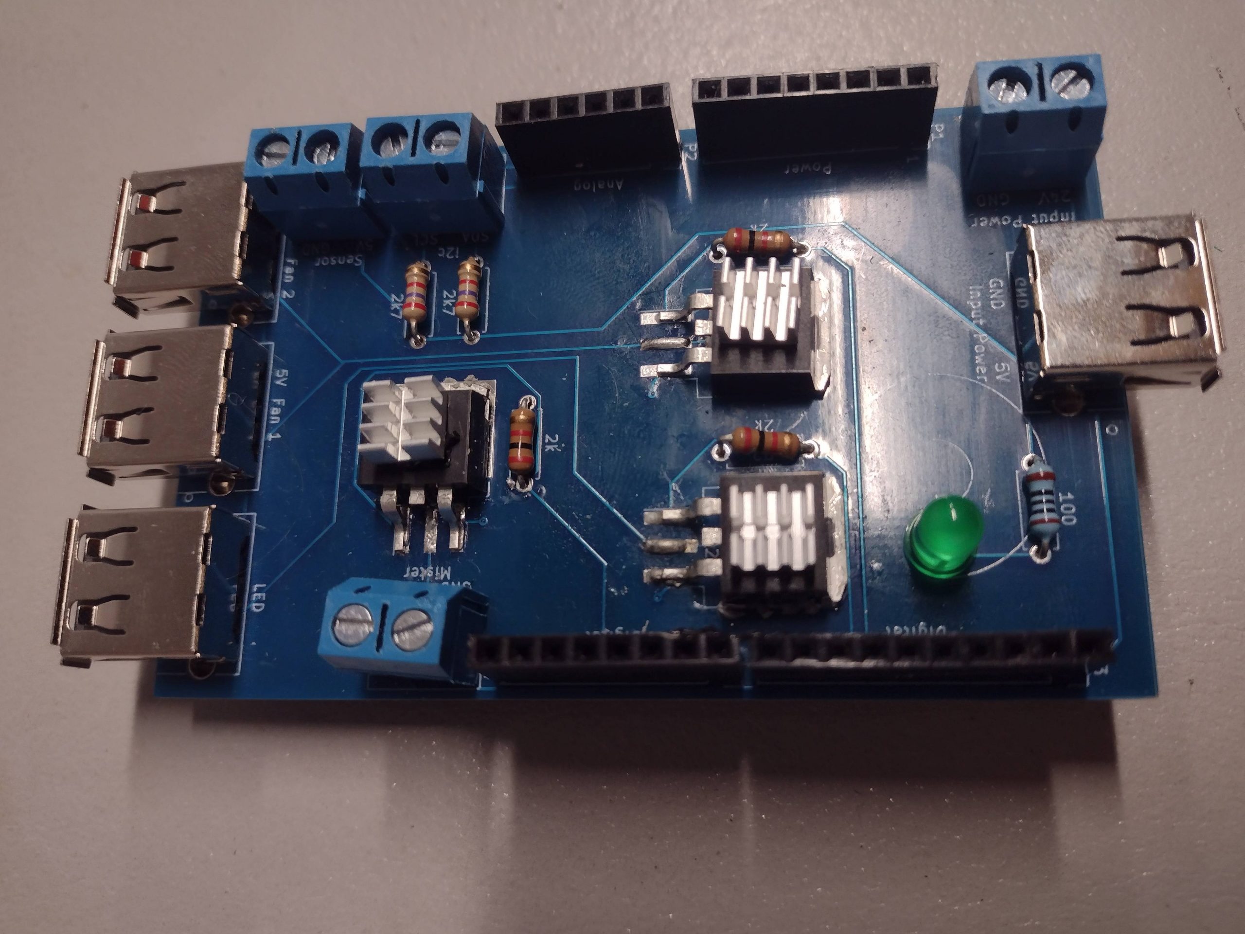
For this project I was aiming to use mostly off-the-shelf parts and Arduino shields, stacking them as needed. Still, I need to handle connecting the devices to control to the Arduino in a relatively solid way. That’s where the custom shield come in: it’s mostly a bunch of connectors with the circuitry to control them from the Arduino. I also added in a LCD shield to see the current status of the sensors.
You can see the schematic, PCB design and Arduino sketch on my GitHub: https://github.com/CindyPotvin/OysterControl
Shield concept
The shield connects the following components to the Arduino:
- A CCS811 air quality sensor that is used to check the level of carbon dioxide in the box. Mushrooms emit CO2 like humans, and don’t grow well when there is too much CO2. When the level is too high, the Arduino will start a pair of fans to move the stale air outside the box.
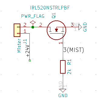
- A BME280 temperature and humidify sensor. When the humidity goes down too much, the Arduino will start a small 24V humidifier.
- The LED strip will be turned on at all time to bring some light to the mushrooms, but it could also be controlled by the Arduino if required.
- The LCD will display the current temperature, humidity and CO2 levels, and the status of the fans and humidifier.
The power sources for all those devices (24V and 5V) are separate from the Arduino power source. I could have gotten the power from the Vin pin for the 5V, but the 24V needs to come from an external supply since it’s higher than the Arduino can handle. Since I’m already messing with external power source, I decided that it would be cleaner if all devices worked that way, and it gives me more options if my current devices are not enough to do the job and I need to draw more current.
I was able to find a LED strip and fans that were already USB, so those devices are also plugged in using USB port to the shield. Everything else is connected using small screw terminal blocks, so it’s still pretty convenient to work with. The external sensor wiring is done using spare ethernet cable.
The humidifier, the pair of fans and the LCD are each controlled by the Arduino using a IRL520 MOSFET:
Shield Schematic
To design the schematic and the PCB for the shield, I used KiCad as in my last project. As a starting point, I used the built-in template in KiCad for an Arduino shield under File/New Project/New Project from Template, and selected Arduino Uno. The template comes with:
- Pre-labelled headers in eeschema with all the Arduino pins (the ones that are not used can be marked as unconnected). You can then fill in the rest of your design in eeschema.
- The shape of a standard shield in pcbnew, including the holes. It also indicates to where the USB port and power barrel of the Arduino will be so you don’t put components that are too big over them.
Since I was also using a LCD Keypad shield, I had to make sure I was not reusing the same I/O pins. In my case, I had no worries about the power since all my devices are powered separately: I have more than enough to spare for the rest of the project. Another advantage of having an external supply for everything!
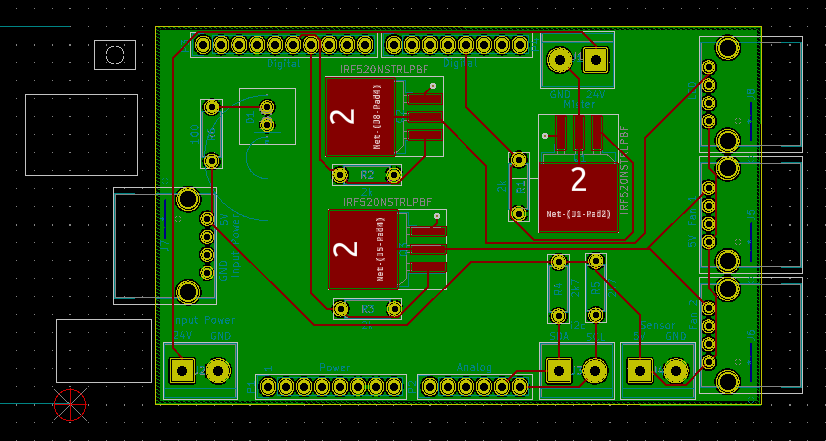
Shield PCB Design
The part that required the most planning was the size of the shield and the components since I wanted to be able to stack my shield using the standard headers. I’m also using the LCD Keypad shield, which obviously goes on top, so I couldn’t use extra vertical space even if I wanted to.
I was a bit short on space trying to keep the shield the size of the Arduino Uno, so ended up making the shield longer than the Arduino. I briefly considered having two shields so I had more space for connectors, but that extra bit of length was enough.
Here are a few more points that helped me:
- Even if there are visible in pcbnew, you still need to be mindful than the power barrel and USB port of the Arduino are really high: you can’t put a through hole component over it or its pins will block the shield.
- Prefer horizontal orientation for components that can be placed in various orientations such as resistors.
- Choose packages that lie flat: TO-220 components are too high if there is another shield on top while TO-263 are really nice for this, even if slightly harder to solder. I have a small hot air rework station that’s really convenient for this kind of soldering.
Now, the only thing left is to wire the whole thing in its final place so I can start testing the mushroom growing. I’ll keep you posted about my progress!