
The i2C protocol is one of the most popular way to communicate with sensors and devices with an Arduino. This protocol was built to limit the pins needed and to standardize the communication so you don’t have to figure out a proprietary format each time. But how to use i2C with an Arduino?
A i2C devices uses two specific pins the Arduino to communicate: one pin is for data (SDA) and the other is for the clock (SCL).
Each device has a specific address, so many devices can be added to the same bus without using up extra pins. The logic level of the communication (generally 3.3V or 5V) depends on the master, so each slave device must be able to work at that level.
Everything is driven by the master node, which generates the clock and manages the communication with all the slave devices. There are theoretically 127 addresses available for slave devices, but you can realistically connect around 6-10 devices. BlueDot has an excellent explanation of what really limits the number of devices at https://www.bluedot.space/tutorials/how-many-devices-can-you-connect-on-i2c-bus/.
If you purchase a sensor with i2c, it will already have a default slave address (the master doesn’t need one). Since each address must be unique, if you want to use more than one of the same sensor on a bus you must make sure that it can be changed by a jumper (or another similar option such as cutting a trace). You also need to be careful that the devices you want to use don’t communicate using the same address.
Adafruit maintains a list of slave addresses for the most popular devices at https://learn.adafruit.com/i2c-addresses/the-list. You should also be able to find it in the documentation for the device, and they often already have an Arduino library that abstracts the messy communication part including the default address to use.
i2c Communication: The Hardware
I2c can also solve the problem of how to connect two Arduino together: the Arduino can act as a master or a slave on the i2c bus. So, for this tutorial, I’m going to make two Arduino communicate, which is also helpful to show how to setup both sides of the communication.
In more common use cases, the Arduino would act as a master, and your other devices, sensors and the like will be slave devices. Those devices will already have its logic and assigned addresses as mentioned previously, so you generally don’t need to setup the “slave” side, but it’s useful to know what it looks like.
In this example, the slave is going to read the value of a potentiometer on the analog pin when the value is requested by the master. Please note that the reverse is possible: a master can push data to a specific slave so it reacts to this data.
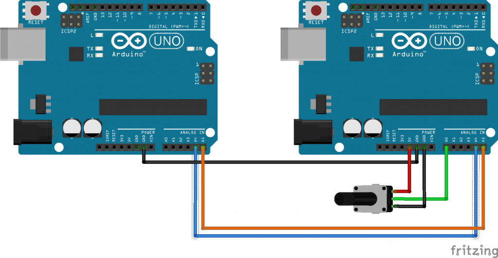
For the Arduinos, the wiring is pretty simple: just wire the SDA, SDL and GND pins of both microcontrollers together. The I2C bus requires pullup resistors (2k7 is usually fine), but they are included inside the Atmega chip of the Arduino and will be turned on automatically by the Wire Arduino library that we will use so you don’t need to add any.
You also need to wire the potentiometer to the A0 analog pin of the slave Arduino so it can have a value to read.
Here is the complete wiring diagram (the potentiometer I used has a maximum value of 1k ohms):
i2c Communication: The Software
First, we’re going to focus on the slave (the Arduino to the right on the schematic). To get started, we need to initialize the i2c communication by specifying the slave address our slave Arduino will have (any value from 0 to 127).
After this, we need to do the setup so the slave will answer when the master requests data. The onRequest call in the setup() method specifies which method will be called to do this, in that case the respondToMasterEvent method.
So, when data is requested, the respondToMasterEvent reads the current value of the analog pin, which can be modified by the potentiometer, and writes it to the buffer so the master can retrieve it. Since the iC2 protocols uses bytes that are 8-bit long, but the analog pin of the Arduino returns a 10 bits value, this value is split in two so it can be sent as 2 bytes.
#include <Wire.h>
// Slave address of this arduino on the bus.
const int SLAVE_ADDRESS = 0x10;
// Analog pin A0 for the potentiometer that will act as an analog sensor in this example.
const int SENSOR_ANALOG_PIN = 14;
// Variable for the current value of the analog pin (declared here to declare it only once).
int analogPinValue;
const int BYTES_TO_SEND = 2;
uint8_t sendBuffer[BYTES_TO_SEND];

void setup() {
  // Enable I2C on the Arduino, including pull-up resistors and join the bus as a slave.
  Wire.begin(SLAVE_ADDRESS);

  // Register event to respond to request from the master.
  Wire.onRequest(respondToMasterEvent);

  // Enable serial for debug information.
  Serial.begin(115200);
}

// This function is called when the master requests data from the slave.
void respondToMasterEvent() {
  // The analog pin can return values from 0 to 1023 (10 bits).
  analogPinValue = analogRead(SENSOR_ANALOG_PIN);
  // Put the value in two uint8_t to send in 8bit format over I2C
  sendBuffer[0] = analogPinValue >> 8;
  sendBuffer[1] = analogPinValue & 0xff;
  Wire.write(sendBuffer, BYTES_TO_SEND);
  Serial.println(analogPinValue);
}

void loop() {
  // Receiving the I2C message has priority over the code in the loop (it works with
  // interrupts), but nothing happens in the loop in this sketch.
  delay(1000);
}
On the master side, we only need to enable the i2c communication. After this, each 5 seconds the master will request the current value of the slave using the slave address according to our code. On receiving the value, it will reassemble it from the 2 bytes it received in a single integer and send it to the serial port so you can see it on the Serial Monitor of the Arduino IDE.
#include <Wire.h>
// Address of the slave on the bus.
const int SLAVE_ADDRESS = 0x10;
// Number of bytes to request from the slave
const int BYTES_TO_REQUEST = 2;
// Last value received from the slave
int slaveIncomingValue = 0;

void setup() {
  // Enable I2C on the Arduino, including pull-up resistors.
  Wire.begin();
  // Enable serial for debug information
  Serial.begin(115200);
}

void loop() {
  // Request 4 bytes from slave device (slave may send less)
  Wire.requestFrom(SLAVE_ADDRESS, BYTES_TO_REQUEST);
  // Read the bytes on the bus, two at a time
  while (Wire.available() >= BYTES_TO_REQUEST) {
    slaveIncomingValue = Wire.read() << 8 | Wire.read();
  }
  // Print the complete value received.
  Serial.println(slaveIncomingValue);

  // Read again from the slave in 5 seconds.
  delay(5000);
}
That’s it: the master can now request data from the slave, and you can see for yourself that the value is updated by changing the value of the potentiometer.
If you wish to download the code example and try to for yourself, it’s available on my GitHub at https://github.com/CindyPotvin/I2C-Tutorial-Arduino